Modular Restroom Unit Installation & Operation Manual
A guided, interactive walkthrough of the installation and operation manual. Use the navigation to move through each deployment stage — from site utilities to commissioning and maintenance.
00
Safety & Site Placement
Read Before Deployment
Read this manual before connecting utilities or placing the restroom into service. Installation, electrical, plumbing, HVAC, lifting, and transport work should be performed by appropriately qualified personnel in accordance with applicable local codes.
Site Placement
Place the container on a stable, adequately supported, reasonably level surface. Maintain access to doors, the rear service area, utility connections, and HVAC openings. Do not position obstructions where they restrict required access or airflow.
Utility Safety
Disconnect electrical power and shut off the water supply before servicing. Do not modify factory-installed electrical or plumbing systems or bypass safety devices. Never energize an empty or partially filled electric water heater.
01
SH-MRU-OVW
Unit Overview
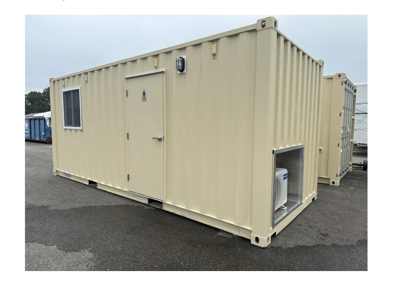
The Modular Restroom Unit is a 20-foot containerized restroom facility engineered for high-traffic, long-duration deployment. Equipment, fixture quantities, and configurations may vary by floorplan.
FIG.01Modular Restroom Unit — exterior three-quarter view
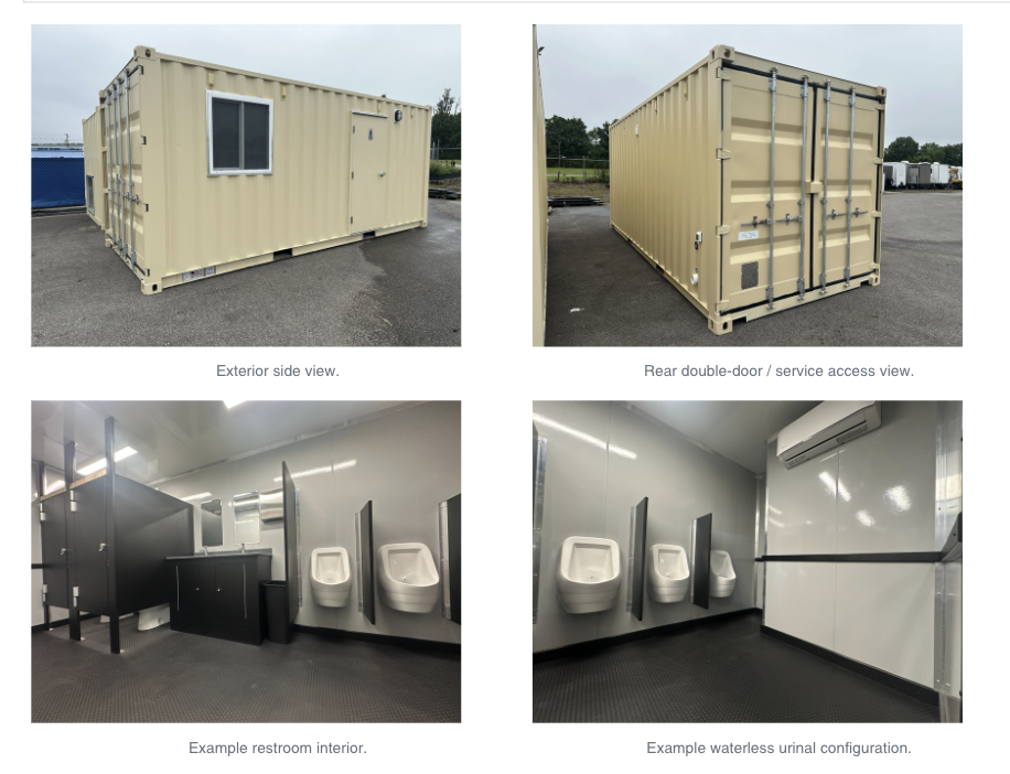
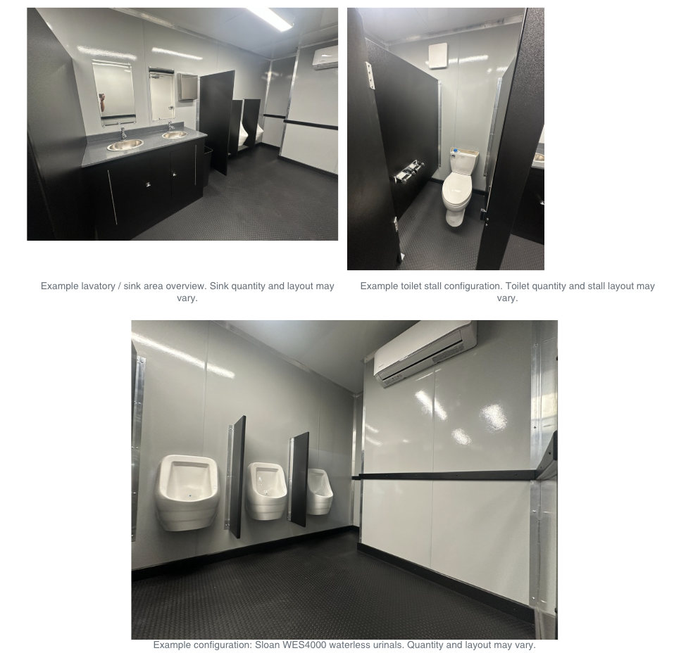
FIG.02Exterior side view, rear double-door service access, example restroom interior, and waterless urinal configuration
Configuration Notice
Equipment, fixture quantities, electrical circuits, plumbing connections, and equipment locations may vary depending on the specific restroom floorplan, options, and configuration. Photographs and diagrams in this manual may illustrate an example configuration. Always refer to labels and equipment installed on the specific unit.
Container Length20 feet
StructureSteel shipping container
AccessRear double-door / service area
ConfigurationsRestroom, waterless urinal, combo
02
SH-MRU-UTIL
Site Utility Connections
Before placing the restroom into service, the customer must provide and connect the required site utilities. Final requirements may vary depending on configuration, site, and locally adopted codes.
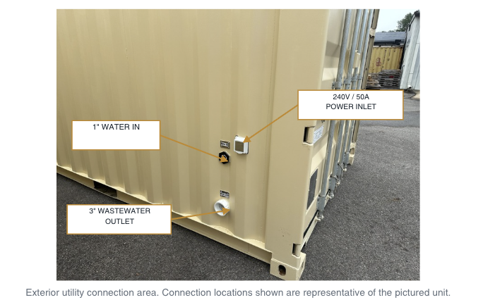
FIG.01Exterior utility connection area — 240V/50A power inlet, 1-inch water inlet, 3-inch wastewater outlet
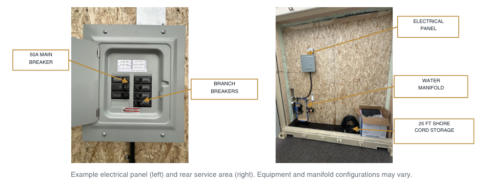
FIG.02Example electrical panel and rear service area — equipment and manifold configurations may vary
Power Inlet240V / 50A
Water Inlet1-inch
Wastewater Outlet3-inch
Recommended Utility Connection Sequence
01
Wastewater
Connect the 3-inch wastewater outlet first. Verify support, continuous 1/4-inch-per-foot fall, and unrestricted drainage.
02
Water Supply
Connect the 1-inch water inlet. Verify 40-80 PSI, slowly pressurize the system, and inspect for leaks.
03
Fill Water Heater
If the heater will be used, place the bypass in normal operation and confirm the heater is completely full.
04
Electrical Power
After wastewater and water systems are verified, connect the supplied 240V / 50A shore cord.
05
Commission Unit
Test fixtures, drains, lighting, HVAC, water heater, and other installed equipment.
Critical — Water Heater Dry-Fire
DO NOT energize the water heater until it is completely filled with water and a steady, uninterrupted flow has been verified at the lavatory faucet. Energizing an empty or partially filled heater can damage the heating element.
The customer is responsible for providing the wastewater piping and equipment between the restroom outlet and the site sanitary sewer, external lift station, or other approved wastewater system. Install horizontal gravity piping with a continuous 1/4-inch-per-foot fall toward the approved discharge point. Avoid backfall, low points, and unsupported sections. The final connection should be designed and installed by a licensed plumber.
Before Placing the Wastewater System Into Service
0/9
2.3 Fresh Water Supply Connection
Connection Size1-inch direct water inlet
Operating Pressure40-80 PSI
Pressure RegulatorNot factory installed
Main ShutoffCITY FILL valve (rear service area)
Final Site ConnectionCustomer provided
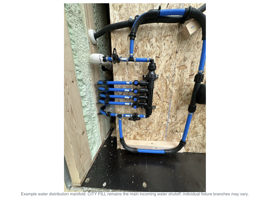
Maintain approximately 40-80 PSI during normal operation. Use appropriately sized piping, hose, fittings, and connections. Provide a suitable pressure regulator when site pressure could exceed 80 PSI. Provide backflow protection where required by applicable plumbing code. The main incoming water shutoff is labeled CITY FILL and is located in the rear service area above the water distribution manifold.
Before Placing the Water System Into Service
0/8
2.4 Water Heater Initial Fill
Dry-Fire Damage
The water heater must be completely filled with water before electrical power is supplied. Energizing an empty or partially filled water heater can damage the heating element.
Initial Fill Procedure
01
Verify Supply
Verify the restroom water supply is connected and the CITY FILL valve is open.
02
Set Bypass
Place the water-heater bypass valve(s) in the normal water-heater operating position.
03
Open Faucet
Open/activate the lavatory faucet.
04
Clear Air
Allow water to flow until a steady, uninterrupted stream is present and trapped air has been cleared.
05
Inspect
Inspect the water heater and accessible piping for leaks.
06
Energize
Only after the heater is confirmed full, supply electrical power to the water heater.
2.5 Electrical Power Connection
Electrical Service240V / 50A
PhaseSingle phase
Connection50A RV-style shore-power system
Supplied Cord25-foot, 240V / 50A shore cord
Final Site PowerCustomer provided
The customer is responsible for providing a suitable site electrical source and compatible outdoor-rated receptacle. If the site is not already equipped, a licensed electrician should provide the required service in accordance with applicable local electrical code.
03
SH-MRU-WTR
Water Distribution System
The water distribution manifold routes supply water to each fixture through individually valved branches. The manifold is located in the rear service area.
FIG.01Water distribution manifold — CITY FILL main shutoff and individually valved fixture branches
Manifold LocationRear service area
Main ShutoffCITY FILL valve
Branch ValvesIndividual fixture shutoffs
Operating Pressure40-80 PSI
Each fixture branch is valved at the manifold, allowing individual fixtures to be isolated for service without shutting down the entire system. Manifold configuration and labeling vary by floorplan. Verify valve labels against the installed unit before servicing.
Routine Verification
0/4
04
SH-MRU-LAV
Lavatory & Water Heater
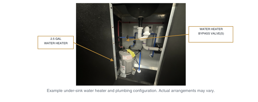
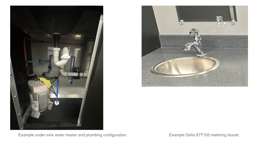
The lavatory is served by an under-sink electric water heater with a bypass valve arrangement that allows the heater to be isolated for service.
FIG.01Under-sink 2.5-gallon water heater and plumbing configuration — actual arrangements may vary
FIG.02Under-sink water heater and Delta 87T105 single-temperature metering faucet installation
Heater TypeElectric tank
Capacity2.5 gallons
LocationUnder lavatory
BypassHeater bypass valve(s)
The water heater provides on-demand hot water to the lavatory faucet. The bypass valve allows water to flow to the faucet even when the heater is isolated for service or replacement. Always confirm the heater is completely full before energizing.
Heater Isolation
When placing the bypass in service position, confirm the heater is full before restoring power. Never energize an empty or partially filled heater.
05
SH-MRU-FIX
Restroom Fixtures
Fixtures vary by floorplan and may include flush toilets, waterless urinals, and lavatory sinks. All fixtures are commercial-grade and engineered for heavy daily use.
Flush toilets are served by the building water supply and drain to the 3-inch wastewater outlet. Waterless urinals, when equipped, drain by gravity to the same wastewater system and require no water connection. Fixture quantities and locations vary by floorplan — always refer to the installed unit.
06
SH-MRU-HVAC
HVAC System
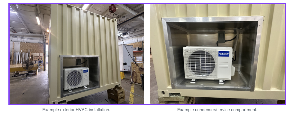
The HVAC unit provides heating and cooling to maintain interior comfort. The wall-mounted unit is controlled by an interior thermostat.
FIG.01Exterior HVAC installation and condenser/service compartment
Unit TypeWall-mounted HVAC
ControlInterior thermostat
Power240V / 50A circuit
Filter AccessFront panel
Set the thermostat to the desired mode (heat or cool) and temperature. The filter is accessible through the front panel and should be inspected and cleaned regularly. Maintain clearance around the exterior condenser opening — do not position obstructions where they restrict airflow.
HVAC Verification
0/4
07
SH-MRU-START
Initial Startup / Commissioning
After all utilities are connected and verified, commission the unit by testing every installed system before placing the restroom into normal service.
Commissioning Sequence
01
Verify Utilities
Confirm wastewater, water, and electrical connections are complete and verified.
02
Test Fixtures
Operate each toilet, urinal, and lavatory. Confirm flush, drain, and flow.
03
Check for Leaks
Inspect all accessible plumbing connections and the manifold.
04
Test Water Heater
Confirm heater is full, then energize. Verify hot water at the lavatory.
05
Test HVAC
Run heating and cooling cycles. Confirm thermostat response.
06
Verify Lighting
Confirm all interior lighting operates.
07
Sign-Off
Document completion and place the unit into service.
08
SH-MRU-WINT
Winterization & Freeze Protection
Freezing temperatures can damage plumbing, tanks, and fixtures. Freeze-protected units are engineered for cold climates, but shutdown in freezing conditions requires proper winterization.
Heat-traced supply lines, insulated tanks, and heated interiors protect the system during operation. If the unit will be shut down in freezing conditions, the water system must be drained and protected to prevent damage.
Winterization Checklist
0/6
09
SH-MRU-MAINT
Preventive Maintenance
Regular maintenance preserves performance, extends service life, and prevents costly failures. Follow the schedule below for routine care.
DailyClean and restock
WeeklyInspect fixtures, check for leaks
MonthlyHVAC filter, water heater check
QuarterlyFull system inspection
AnnualComprehensive service
Daily cleaning and restocking keeps the facility serviceable. Weekly inspections catch leaks and fixture issues early. Monthly HVAC filter checks maintain airflow and efficiency. Quarterly and annual inspections should be performed by qualified service personnel.
10
SH-MRU-MOVE
Shutdown & Relocation
When a project ends or the unit is redeployed, follow the shutdown and relocation procedure to protect the unit and prepare it for transport.
Shutdown & Relocation Sequence
01
Winterize
If freezing conditions are possible, complete the winterization checklist.
02
Shut Off Utilities
Disconnect shore power, shut off water at CITY FILL, and cap wastewater.
03
Drain Systems
Drain water heater, lines, and traps as required.
04
Secure Interior
Secure fixtures, close doors, and lock access points.
05
Lift & Transport
Use appropriate lifting equipment and transport per container guidelines.
11
SH-MRU-TROUB
Troubleshooting
Use the guide below to diagnose common operational issues. If the issue persists, contact SteelHart support.
Problem
Likely Cause
Action
No water flow at fixtures
CITY FILL valve closed or low site pressure
Open CITY FILL valve; verify 40-80 PSI at supply
Water heater not heating
Heater empty, no power, or tripped reset
Confirm heater is full; verify power; press reset button
HVAC not running
No power, thermostat setting, or clogged filter
Verify power; check thermostat; clean or replace filter
Tighten connection; isolate at manifold; replace valve if needed
12
SH-MRU-PARTS
Replacement Parts & Documentation
Replacement parts and equipment documentation are available through SteelHart. Maintain records of installed equipment and service history for warranty and support.
Each unit ships with equipment documentation for installed components — water heater, HVAC, fixtures, and electrical devices. Retain these documents for reference. For replacement parts, contact SteelHart with the unit spec code and a description of the required component.
Parts SourceSteelHart Fabrication Co.
Contact+1 (574) 403-8799
Emailsupport@steelhartfab.com
DocumentationRetain shipped equipment manuals
Need Support on This Deployment?
Our engineering team is available to walk through installation, commissioning, or any technical question on this unit.